
A diamond vibrating membrane and its manufacturing method, passing a non-uniform energy (such as thermal resistance wire, plasma, flame) that excites dissociated gas above a mold, using the distance between the curved surface of the mold and the non-uniform energy that excites dissociated gas Differences form different heating effects. When the diamond material is coated on the surface of the mold, the growth of the diamond material is different, so that the diamond vibration film has non-homogeneous vibration characteristics, so that the diamond vibration film has a wider audio bandwidth.
When selecting the material of the diaphragm, the main considerations are hardness and damping characteristics. The hardness determines the natural frequency of the material, and the natural frequency of the material with high hardness is relatively high, and vice versa, the natural frequency of the material with low hardness is also low. Materials with good damping characteristics can make the vibrating membrane have a smoother vibration response, making the output sound pressure level of the vibrating membrane smoother.
Traditionally common vibrating membrane materials include paper, polymer plastic materials, metals (Be, Ti, Al), ceramics, etc. Paper and polymer materials have good damping characteristics, but poor rigidity and easy damage, and low hardness is not enough to make them The maximum operating frequency is limited. Although the metal vibrating film has better hardness, high-hardness metals such as Be, Ti, etc. are expensive and difficult to process. Ceramic materials also have the problem of complicated sintering procedures. Due to the excellent mechanical properties and strength of the diamond material, it is suitable for the manufacture of light-weight, high-rigidity diaphragms, and can be used in mid- and high-frequency speakers. The desired sound is generated through the vibration frequency of the diaphragm. The higher the vibration frequency of the diaphragm, the stricter the mechanical strength and quality requirements of the diaphragm, and the use of diamond materials to make the diaphragm can achieve this goal.
Generally speaking, the vibrating membrane has an upper limit of the response frequency. However, regardless of whether the vibrating membrane is made of diamond or other materials, the natural frequency is limited to a specific range due to the uniform overall material properties, which limits its bandwidth performance. The damping characteristics and rigidity cannot be changed arbitrarily, which limits its sound quality and timbre performance. Therefore, if you want to cover the frequency range acceptable to the human ear, you usually need to set multiple diaphragms with different bandwidths and frequency upper limits at the same time to achieve the best sound effect. Therefore, in the prior art, there is a technology of using different materials to make the vibrating membrane in sections. The central part of the vibrating membrane is made of a material with high hardness, and the outer ring is made of a material with low hardness. Then these two parts are joined to make a single The vibrating membrane has two different material hardnesses and thicknesses at the same time, and can cover a larger bandwidth. However, the thickness of the vibrating film is usually extremely thin, and the joining work is difficult. If it is to be applied to diamond materials, its bonding technology and bonding agent are very big problems, so it is not easy to apply to diamond materials.
In order to solve the above problems, the present invention proposes a diamond vibrating film and its manufacturing method, which can change the hardness, thickness and damping characteristics of different regions on the diamond vibrating film, so that it has non-uniform vibration characteristics and covers a large frequency range. .
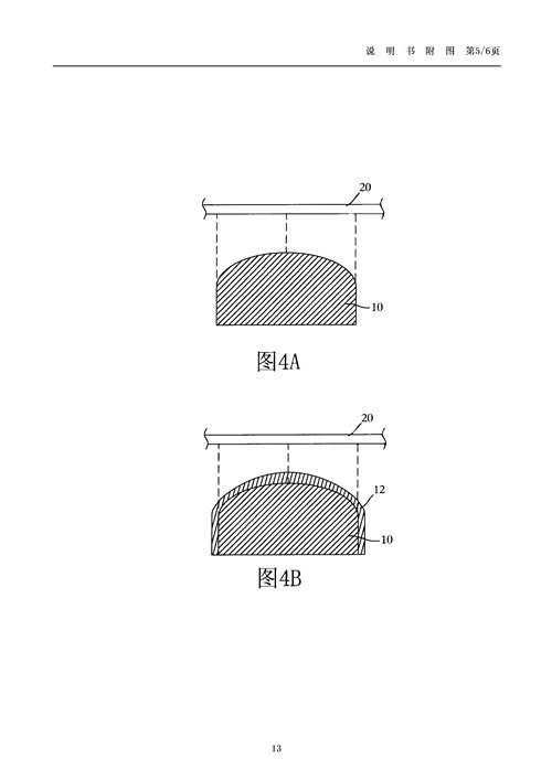
According to the diamond vibrating membrane and its manufacturing method disclosed in the present invention, a mold with a curved surface is provided, and a non-homogeneous (non-homogeneous) energy that excites a dissociated gas passes through the top of the mold to generate high temperature to heat the mold so that the surface of the mold is presents an unequal temperature distribution.
For example with
1. The thermal resistance wire is the center point (the highest energy area), and the concentration of the reaction substance presents an uneven ring distribution.
2. Due to the effects of wavelength, amplitude, and standing waves on the plasma excited by high-frequency energy, the concentration of reacting substances presents a spherical shape with non-uniform distribution.
3. The flame energy decays outward from the central area, and the concentration of reacting substances presents an uneven divergent distribution.
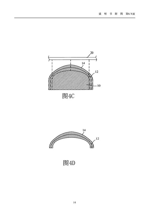
The temperature and reaction substance concentration generated by the above energy decay rapidly outward in sequence; therefore, different mold surface positions contact with different regions of reaction substance concentration to grow diamond films with different structural states and different thicknesses, making the diamond material have non-uniformity. (non-homogeneous) vibration characteristics, such as thickness or hardness present non-uniform distribution, and then the diamond thin film is removed from the mold to form the diamond vibration film. The structural states of diamond materials include micro-crystal (Micro-crystal), nano-crystal (Nano-crystal) and so on.
According to the diamond vibrating film manufactured by the present invention, its hardness and thickness are not uniform, and the hardness of the middle area is high, the hardness of the edge area is low, and the thickness of the middle area is large, and the thickness of the edge area is small. The vibration characteristics of each part are affected by the hardness and The effect of thickness has different natural frequencies respectively, so that the diamond diaphragm can have a larger bandwidth.
Description of drawings
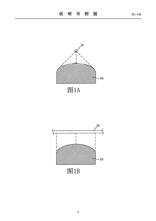
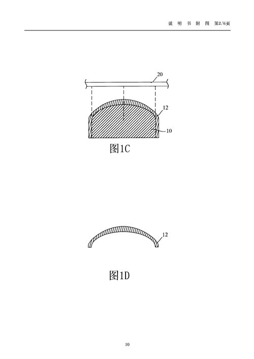
1A-1D are schematic diagrams of the production process of the first preferred embodiment of the present invention;
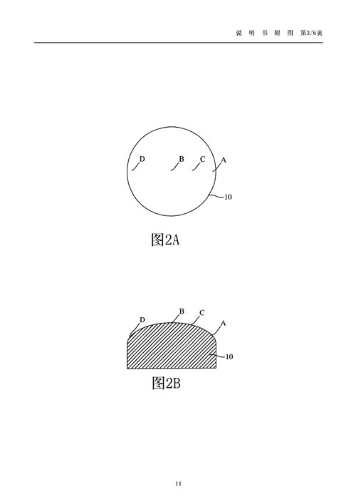
Fig. 2A is the top view of the mold of the first preferred embodiment;
Fig. 2B is the side view of the mold of the first preferred embodiment;
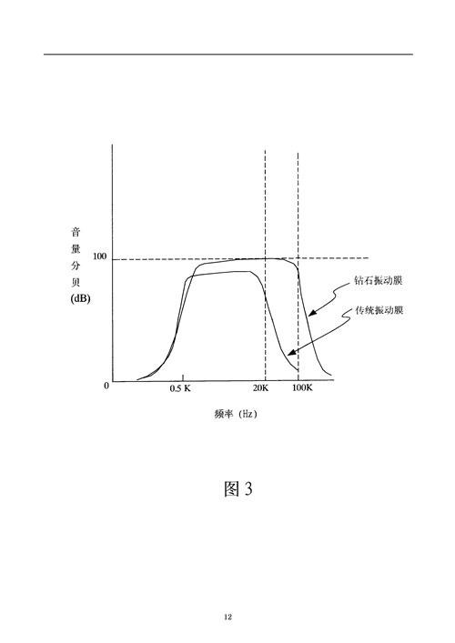
Fig. 3 is the frequency, volume analysis figure of the first preferred embodiment and prior art; And
4A-4D are schematic diagrams of the manufacturing process of the first preferred embodiment of the present invention.
Among them, reference signs:
10 molds
12 First Vibrational Layer
14 Second Vibrational Layer
20 thermal resistance wire
A, B, C, D mold surface
Post time: Jun-30-2023